 Point ownership
![[MAT logo]](../../../images/MAT-linux-h100.gif)
Points may be 1-bit, corresponding to discrete inputs, outputs, internal/memory coils, flags etc, or multi-bit (up to 32-bit), corresponding to analog inputs, outputs, integer or floating point registers etc.
Points are defined in the PLC section of the config.
 Point ownership
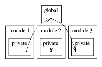
The diagram on the right shows the situation for one point and three modules: the point is owned by module 1. It has a private copy of the point, and is allowed to write to it. At the bottom of the scan, the point is copied to the global area, from which it is copied to modules 2 and 3 at the top of their scans.
This means that while troubleshooting, if the point has an incorrect value, we know to check module 1.
For instance, in the basic demo, there are the following points:
L1, L2, L3, L4
left, right quit The declaration in the config file looks like this:
point L1        "light 1" Chaser
point L2        "light 2" Chaser
point L3        "light 3" Chaser
point L4        "light 4" Chaser
point left      "<- (key L)" Kbd
point right     "-> (key R)" Kbd
point quit      "quit (key Q)" Kbd
All of the points are also displayed on the screen, by the vitrine module. No special access configuration needs to be done to allow this - any module may read any point it wishes; it's only changing them that's restricted.
In the modbus demo, the
L1, L2, L3 and L4
points are also sent to the Modbus slave.
A: In the MatPLC, all modules are written by one module (the "owner") and read by all modules. There is no way to have a point that could be written by two modules which are both active at the same time.
It's probably better to have a separate point for each module that wants to write, anyway, and then have explicit logic deciding between those values. That way if the wrong value comes out, you know where to look for the problem...
For instance, you might have:
foo_auto
foo_manual
if automatic_mode
    then copy foo_auto to foo_cur
    else copy foo_manual to foo_cur
foo_cur
$Date: 2006/03/06 04:20:16 $